
|
|
|
The Aeronca Champs and Chiefs use the "famous Aeronca oleo landing gear", featuring a hydraulic shock strut with an internal spring. As further explanation - here's the definition of "oleo strut" from the Random House Dictionary: oleo strut, a hydraulic device used as a shock absorber in the landing gear of aircraft, consisting of an oil-filled cylinder fitted with a hollow, perforated piston into which oil is slowly forced when a compressive force is applied to the landing gear, as in a landing.I admit I've applied some substantial "compressive forces" to the landing gear on my Aeronca. It's a great landing gear, but it does need regular maintenance. And after 60 plus years, there are some things to look for. I knew that the oleo struts on my Chief had been rebuilt with new bushings just three years prior, but even so, not all was quite as it should have been. What follows is based on my experience. It should help you understand how the oleo struts are put together and serviced. Before you tackle your struts, read this entire web page - because what follows does not necessarily proceed in step-by-step order. You should also carefully read the Aeronca Service Manual. All work should be performed or supervised by an FAA certified airframe mechanic, and the proper logbook entries should be made. One more note: much of the material here applies only to the standard oleo strut landing gear, not the "no bounce" landing gear offered later and found on some Aeroncas. Among other differences, the "no-bounce" gear uses a different, longer but smaller diameter spring that will not work properly in the standard strut. The "no-bounce" landing gear can be identified by a "bulb" located at the lower end of the oleo strut assembly. Click for the no bounce drawing and no bounce parts list. The image below is a scan of the cylinder portion of the standard oleo case frame from the Aeronca Chief Service Manual.
After moving to a new hangar with a nice level floor, I noticed that the right wing on my Chief sat lower than the left. In fact, near the wing tip, there was about a 5 inch difference, measuring from the tip at the aileron straight down to the floor. I suspected a weak oleo strut spring on the right side. From the experts on the Fearless Aeronca Aviators mailing list and elsewhere, I learned to check a number of things, other than weak springs, that COULD cause the wing-low condition:
Convinced that the problem probably was a weak spring, I called Safe Air Repair for a pair of new springs and new packing. The part number for the springs is 1-2256. The packing is part number 1-2119. Cost for everything, with shipping, was a little over $100. Safe Air Repair had a great reputation for quality and service. During March of 2005, Safe Air Repair was sold to Wag Aero and they now carry the Safe Air inventory. Univair is another source for parts, and I have been very happy with the quality of their parts. Service procedures for the oleo struts are found in the Service Manual, but it helps to know a few tricks not found in the manual. Regarding the packing, McMaster-Carr may also be a good source. More details about that can be seen further along on this webpage.   Speaking of parts, when you have things apart, check the condition of the retainer at the top of the oleo strut. This is part number 1-316 in the drawing. Aeroncateer Carl White passed along the following information: "I've seen some of the aluminum top retainers that did not have a bevel cut on the spring side as well as some of the really old phenolic types. Think most of the current replacement items have the bevel. If one runs into a retainer that has mushroomed and does not have the bevel, about all that one can do is to use a slide hammer to pull the retainer out of the cylinder past the bushing. Several bad things can happen if brute force is required, the worst is that the bronze bushing will be pulled out along with the retainer. If this happens, the likelihood of the reuse of the bushing is remote. Wish someone smarter than me could figure out a way to remove a damaged retainer without doing harm to the bushing. Bushing replacement is not a fun thing . By the way, if one encounters one of the original phenolic retainers, I would suggest replacement with the "modern" aluminum type." And speaking of replacement parts, early Champs and Chiefs had a "laminated synthane" fiber piston head as part of the 1-2255 piston rod assembly that should have been replaced long ago with an aluminum piston head. This was addressed by Airworthiness Directive 47-20-02 which applies to 7AC airplanes having serial Numbers 226 to 3721 and 11AC airplanes with serial numbers 1 to 351. This replacement should have been done "not later than August 1, 1947," so you should not have a fiber piston head on the oleo strut assembly your airplane. (The AD does not apply to the later "No Bounce" oleo struts that did not have the fiber piston head). Regarding that airworthiness directive, oleo expert David Rude offers this clarification: "Yes there is an Airworthiness Directive (AD) and a Service Bulletin (SB) on this oleo. Occasionally there is confusion over what part the AD is referring to. The SB makes it very clear, the AD is a little sketchy. The AD is not referring to the "donut" on top of the spring that is plainly visible (part number 1-316). Apparently that part came in fiber or aluminum as mentioned previously and that perhaps is why it is mistaken for the part referred to in the AD. The AD does refer to the piston inside the oleo you cannot plainly see. You have to drain the oil, remove the spring then slide the rod all the way down and look in the filler hole to see the part covered by the AD. You may have to clean all the gunk out to see what you're looking for, but look for a shiny aluminum surface (rather than a dull fiber one). I use a penlight to shine in, makes it easier to see. If you see fiber you need a snare cable or replace the piston."
Here's one additional note on parts that I
learned from Dave Rude. The aluminum 1-319 packing gland is available from
both Univair and Wag-Aero. The Univair packing gland will need to be
reamed to fit over the piston rod, the Wag-Aero packing gland comes ready to
install. Need a Lift? Servicing the struts requires that the plane is supported so that the landing gear is not under load and is off the ground. There are several methods that can be used for this, and what works best for you may be different than the method I used.
    Here's another variation on the same theme, this arrangement by Dan Jones from Alberta, Canada. He actually used a combination of methods two and three. It helps to have a spare Continental W670 radial laying around the shop to use as "dead weight". Dan explains: " "The A frame trestle is 2x4's bolted together for stiffness and it's the absolute bare minimum height for a Champ, 87" from the apex of the saddle to it's base. You can't swing the gear leg out - I opted just to remove the case frame completely - my logic being that the lesser the angle I had to trestle the airplane at the less load I'd put on the other gear leg and it's packing. I jack the airplane with a small jack and then slip the trestle in place and lower the airplane down onto the free standing trestle. Then I use a heavy weight (I used a time-expired W670 Continental) tied down to the low wing's tie down point in case the trestle slips. It's all very easy to do solo."
But before you lift that baby... Remember that we're working with springs here, and that can be tricky. You will need a way to compress the new spring so that you can install it on the strut. You may as well get ready for this before you start taking things apart. The new springs I received were 11 1/16" tall. To fit them on the strut you will need to compress them to about 10.5 inches. The method I used successfully was recommended by Aeroncateer Richard Jeffryes. It worked great. I went to my local hardware store and bought a half inch threaded rod, 2 feet long, with nuts and washers. I ran the rod through the new spring, with a nut and washer on each end. After tightening the nut so that the spring was compressed to about 10.5 inches, I used safety wire wrapped though the coils to hold the spring in the compressed state. Then I loosened the nuts and removed the threaded rod. Cool - I now had a shorter spring that I could fit onto the strut piston rod with no pain. The first photo below shows the spring compressed using the threaded rod. The second photo shows one spring "au natural" and the second held in the compressed state with safety wire. I used a safety wire in three different places around the circumference of the spring. For safety, it would be better to use double or triple wraps of safety wire, rather than the single wrap shown here. If a wire fails, it could cause injury. Also, when I've done this recently, I've used safety wire in FOUR places around the circumference. The old spring that I removed was 10.5" long, 9/16" shorter than the new spring. Richard Jeffryes has measured a couple of new springs and they were 11 1/8" tall. Richard Murray says the new springs he received from Wag Aero were 11 1/4" tall. 
 There are other methods that work for compressing the spring; creativity is encouraged! Aeronca owner Carl White likes to use a 36" bar clamp. He reports: "I use a 36" bar clamp to compress the spring enough to remove and replace the upper pin. The trick is to get the retainer to slide in the spring while keeping the alignment with the hole in the shaft. I find it best to do it flat on the bench with a sandbag on top of the spring to keep things in place in case the clamp slips. The sand bag is fairly important in case that sucker slips and flies across the shop. I just like the bar clamp method over the safety wire as it allows micro-adjustment of the spring seat. Just crank it in until it fits." I also liked another story from Carl: "I once replaced a spring in the field by jacking up the Suburban and putting the assembly between the frame of the 'burb and the ground and then letting the jack down until the pin could be driven out smoothly. Reversed the process for install. Necessity is a mother!" Aeronca owner and restorer Mike Berg posted a note on the National Aeronca Association Forum in September of 2014. He created a tool to compress the oleo spring while it is on the strut. See photo below. It looks safe and quick. It uses two turnbuckles with eyes, threaded rod, large fender washers, and an aluminum block that he drilled to accept the threaded rod at the top end. Mike tightens the nuts at the top of the block to compress the spring, though one could use a wrench on the turnbuckle instead. If you want to lock the turnbuckles so they don't loosen, you could use a lock nut on each end, but would need a left hand thread turnbuckle nut for the bottom end.
While we're talking about springs, you should know that it is important that the springs not be too short. New springs should be around 11 1/16" to 11 1/4" long. Aeronca owner Richard Jeffryes says, "When they get too short, they can rattle against the piston shaft and wear it, and they can also hammer the top of the oleo." Richard says he has seen spacers made, as well as taller packing glands. But the best bet (and the approved method) is simply to buy new springs. Another thought... it may be best to replace springs on both sides at the same time, as they do tend to get shorter over time. In 2013 I changed the spring on the "low" side on my Champ with a new one. You can guess the results - now the other side was "low." I immediately replaced the other side so things would be "on the level." Time to take things apart - removing the Oleo Piston Assembly
  The Oleo Piston Assembly - the spring thing.... At the top of of the assembly there is an aluminum retainer (part number 1-316) that holds the spring in place. It is attached to the piston rod assembly (part number 1-2255) by a bushing (ASI-5028-1-22) that is driven though the retainer and through the piston rod. Once the assembly is back in the case frame, the AN-4-23A bolt that you removed earlier will go though the case frame, the retainer, the piston rod, and the bushing to hold the entire mess together. To remove the spring, you drive out the bushing. Use a punch or pin that is just under the diameter of the bushing, being careful not to damage the bushing, since you will reuse it. Once the bushing it driven out, the retainer can pop off and you can remove the spring. Assembly works just the reverse, after you installed the compressed spring as shown below. It works best if you take a file and create a slight taper on the edge of the bushing before reinstalling. We found that the piston rod wanted to slide back into the strut cylinder while we were installing the spring. To pull the piston rod back to it's fully extended length, we simply tied a piece of safety wire to the top where the retainer and bushing is attached, and used the safety wire to pull the piston rod to the extended position. Then we were able to easily slide the retainer onto the end of the rod.
But before you put the new spring on, you need to replace the packing. The graphite packing keeps the hydraulic fluid from leaking from the lower hydraulic portion of the strut up into the upper spring portion of the strut. The packing sits in a small cup-like space called the stuffing box and surrounds the piston rod. It is held in place by a clever aluminum retainer called the packing gland, which is shaped so that it forces the packing against the piston rod. Pressure from the spring holds the packing gland in place. With the spring removed, it is easy to pry the packing gland off, exposing the packing and the stuffing box. The packing is like a thick, graphite coated piece of string, and is wrapped around the piston rod in the stuffing box. You'll need to cut the packing to fit. As received from Safe Air Repair, the packing was thicker than the packing I removed. You'll need one packing kit for each strut. The packing gland will sit high, but once everything is back together, it will compress and sit fine. Ideally, after things are back together, the gland should sit perhaps 1/8" or w little more proud of the stuffing box. If the packing gland rests against the face of the stuffing box, it cannot exert pressure on the packing and will leak. The photo on the left is of the aluminum packing gland, bottom side up. It sits on top of the hydraulic cylinder, held in place by the big spring. The beveled shape forces the packing against the piston rod to minimize seepage of the hydraulic fluid around the rod. In the second photo, the packing is partially installed in the stuffing box and Tom is using the knife to mark the packing for final cutting. David Rude says the new packings are not the same size as the originals and will wrap three turns instead of two as shown in the old drawings. My experience is that it depends on the supplier of the packing, or maybe even the particular batch. With some packings, it seems only possible to get one full wrap. John Propst has an excellent article on this topic on his website at this link. See more on packings below.    In May of 2010, I received an email from John Price offering some additional information regarding the packing. First, he provided a PDF scan of an Aeronca Drawing 1-2119, Packing, Landing Gear Oleo Graphite, that provides details of the 3/8" packing installation. See it here. John notes that packing is "available from McMaster-Carr in 5, 10 and 25 foot lengths... 5 feet will cost you a whole lot less than 2 of what Univair or Wag-Aero will sell you... Is it legal to use it?... My take is yes, since 1-2119 specifies "Commercial Product Interchangeable with Johns Manville..."" Here's the link to the McMaster-Carr catalog: http://www.mcmaster.com/#compression-packing/=72krmj See more discussion and photos of packing in my 2013 update at the bottom of the page. Now you can fill the strut with oil. We chose to do this while the strut was on the bench. You could just as easily fill the strut after it is installed back on the airplane. Unscrew the plug, and fill with hydraulic oil. My 11AC Aeronca Manual says to fill with "Teleo" oil or any good hydraulic oil. We used standard MIL 5606 hydraulic fluid. Later, I learned that Carl White suggests using John Deere "Hy-GARD" multipurpose hydraulic fluid. He reports that the John Deere fluid is less messy, tends not to leak as much or leave a residue, and has the same specs as the "approved" Socony-Vacuum "Teleo" oil mentioned in the service manual. Aeronca owner George Edgerton has tried both MIL 5606 and the John Deere "Hy-GARD" and prefers the latter, reporting that "Bottom line is that the struts work extremely well with this oil---light years better than before." Others have suggested motorcycle fork oil. Dave Rude, who rebuilds oleos as a side business, says that he uses MIL 5606. He points out that the 7EC Manual specifies 5606 for the "no-bounce" oleo, and so he keeps a supply on hand and uses it for all of his struts. MIL 5606 is the "standard" and most A&P mechanics are comfortable sticking to that. You may notice some initial leaking after installing new packings. I experienced a bit of leaking at first, but it did not last. Richard Jeffreys reported, "My no-bounce gear did [leak] when I first installed them, but then the packing took a seat and they quit. A little oil looks like a lot." It's important that the strut is filled COMPLETELY with fluid. Lift the strut high enough so that it can be completely filled. An Aeronca Service Letter (#40, September 8, 1948) included the following information: "The landing load factor runs extremely high when the fluid gets low in the oleos - 3/4 full is almost as bad as no fluid at all! Oleos must be kept full of fluid." After filled, of course, screw the plug back in nice and tight. The shot below shows us filling the strut. We used a turkey baster for the job. It worked great. For those of you who may have seen instructions to fill the strut with 8.5 ounces of fluid, you should know that that instruction applies to the "no bounce strut", not the standard strut. If you have the standard strut, fill it up! By the way.... there have been reports of major damage to the oleo assemblies from lack of oil. Some Aeronca owners have reported that the upper retainer will "mushroom" from the pounding it receives if the strut does not have enough oil. If this happens, repairs are difficult and expensive.  In February, 2011, David Rude posted the followng note about oleo oil on the Fearless Aeronca Aviators discussion forums:
About that plug... The little plug at the bottom of the strut fits into a hole with a 1/8" NPT thread. Be sure you are using the correct size plug. My Chief has brass plugs, though one owner has suggested using a steel plug. Using a plug of a softer metal than steel (brass or aluminum) offers several advantages: less chance of damage to the strut from cross threading, less likelihood of the plug welding itself to the strut, and the ability to seal better with less torque. It would also be easier to drill out a damaged brass or aluminum plug than a steel plug The style of plug seems to vary. My plugs were simply slotted for a standard screw driver. Many have the square head plug - an AN913-1 or MA20913-1 type. Highly recommended is a brass plug with an internal wrenching hex head for use with an allen wrench. These are available from McMaster-Carr, part number 9171K251, and use a 3/16" allen wrench. I ordered some and will use them the next time I refill the struts. David Rude likes to use an AN932-2D aluminum plug, also referred to as an MS27769-2D hex plug. In any case, some thread sealer, such as Loctite 565 NST or Tite Seal compound, is a very good idea. A leak that you might think is coming from the graphite packings - and thus prompting a complete disassembly of the strut to replace the packings - could be from something as simple as a leaking plug. Don't ask me how I know. Back Together... Once the assembly is back together, just slide it back into the case frame. You might need to wiggle it a bit. Be SURE that you get things lined up so that the AN4-23A bolt at the top of the strut goes through the bushing and the retainer. You must insert the oleo strut far enough into the case frame for the bolt to engage the strut. If the bolt misses its mark, your landing gear will fall off when you take off, very embarrassing. Also make sure that the fill plug at the bottom of the strut is in the up (or outboard) position, so it can be checked and filled as necessary. Re-attach the axle with the AN6-23 bolt (with the washers in the right place and the wheel pant bracket in place). The bolt should be snug enough so there is minimal play, but loose enough that the axle can pivot.
With everything back together, look for the Alemite (Zerk) grease fitting on the front lower end of the oleo case assembly. The Chief Service Manual says to apply AN-G-3a or AN-G-15 grease (apparently no longer available) with a gun until it is forced out of the bottom of the oleo case assembly. I just used the general purpose water-resistant grease that was in my grease gun. If you want to buy aviation grease, Aeroshell 22 or Aeroshell 6 would be appropriate. On the lubrication chart published by Shell in 1948, they indicate Aeroshell Grease 6 in the Aeronca Oleo Assembly Piston. Carl White says he does not trust the Zerk fitting to lubricate the full circumference of the strut, and instead gives the strut a light coat of grease before installing it (after carefully cleaning the case). Carl also suggests lightly coating the spring. Don't get carried away with the grease gun - a few shots should do it if you have given the strut a light coat of grease before installation. I heard a story of someone using two cartridges of grease with an air-powered grease gun. In this case, the grease found it's way up into the spring area, completely filling it, and eliminating all chance for the strut to work properly. So... don't take at face value the instruction in the Service Manual to apply grease "until it is forced out of the bottom of the oleo case assembly." Most people recommend 4-5 shots of grease, assuming you have greased the strut before inserting it into the case frame. At any rate, with the strut lubricated and installed, you're done. Now check those measurements again. Is your Aeronca on the level? With the new spring installed, mine was.Postscript... After less than two years with the new spring on the Chief, (I only installed a new spring on the right side), I noticed my right wing was down again, and the oleo strut was showing evidence of a weak spring - again! In fact, it it had gradually been getting lower and lower over the last year or so. A check with the tape measure showed the right wing was again about 5 inches lower than the left at the tip. What's going on? At Oshkosh 2005 I spoke with Mike Utley of Wag Aero about the problem and he followed up with Joe at Safe Air Repair. The word is that around 2000 or 2001 there was a batch of springs that were slightly undersized in thickness, and so were not quite up to specs. Safe Air sent out new springs to those who ended up with the bad springs. Apparently the ones I received were in that weak batch and I missed out on getting replacement springs. Mike explained all of this when I called in late August 2005. He assured me that the springs now in stock at Wag Aero met specs, so I ordered another 1-2256 spring and the 1-2119 packing kit. Prices at Wag Aero were good and service was very good as well. By the way, Mike Utley would be a good contact at Wag Aero if you have questions about Aeronca parts or about the transfer of Aeronca related parts to Wag Aero from Safe Air Repair. His phone number is 1-800-558-6868 (Ext. 142). E-mail is mutley@wagaero.com. While waiting for the new parts, I stopped at my local John Deere dealer and picked up a gallon of Hy-GARD hydraulic oil. Part number for this oil, promoted as a multipurpose "Transmission and Hydraulic Oil," is TY6354 for the gallon jug. Cost for the gallon was $7.77, a bit less expensive than buying MIL 5606 by the quart from the aircraft supply houses. The parts came from Wag Aero quickly, but I procrastinated about doing the work. Finally, a month later in October, 2005, I got to work. I decided to use a hoist (also called a shop crane) this time, and found one on sale at my local Harbor Freight store. Seemed like a good investment, since I will use it often enough. This made the job much easier, and enabled me to do thejob "solo". I used a heavy duty nylon "tow strap" that I picked up at the local hardware store. After fretting about this, my friend Claudio tied a nice double knot in the strap to shorten the working length to about two feet. I slipped this under the engine mount tubes where the mount meets the engine. To help stabilize the aircraft, I chocked the tail wheel. I also used a tie-down strap between the opposite wing tie-down ring and a heavy stationary object on the floor (my air compressor served the purpose) to help keep the opposite wing low and to further stabilize the airplane when hanging from the hoist.
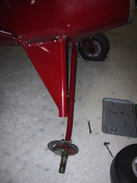
This method of lifting the aircraft worked great and I was able to lift the plane high enough that I could swing the strut out without removing the wheel assembly from the axle. Since the packing had been recently replaced and was well seated, I decided not to replace the packing this time, but simply replaced the spring with the new one. Again I used the safety wire method to compress the spring. Everything came apart and went back together easily and quickly. I drained the old hydraulic fluid from the strut and replaced it with John Deere Hy-GARD hydraulic oil. I cleaned out the case and spread a layer of grease on the strut before reinstalling. After five shots with the grease gun, I was good to go. Measuring the distance from the floor at the wing tips, the plane was once again "on the level." More on Oleo Struts - 2013 Update I've been doing more work on oleo struts this year as I work on the Champ I bought recently. I continue to learn new things.
These photos show how I now lift the plane. I find it works best lifting via the motor mount at the firewall, rather than at the engine as I had done previously. The angle is better. Wrap the strap below the lower tube and it can't slide.
I talked to Dave Rude about this, and it is something he has seen before. If the packing gland is not replaced, the spring could contnue to beat against the packing and eventually beat a hole in the bottom of the stuffing box. I ordered new packing glands from Wag-Aero, PN 1-319 for both struts. I also took care to inspect the stuffing box after removing the packing. Thankfully there was no damage there.
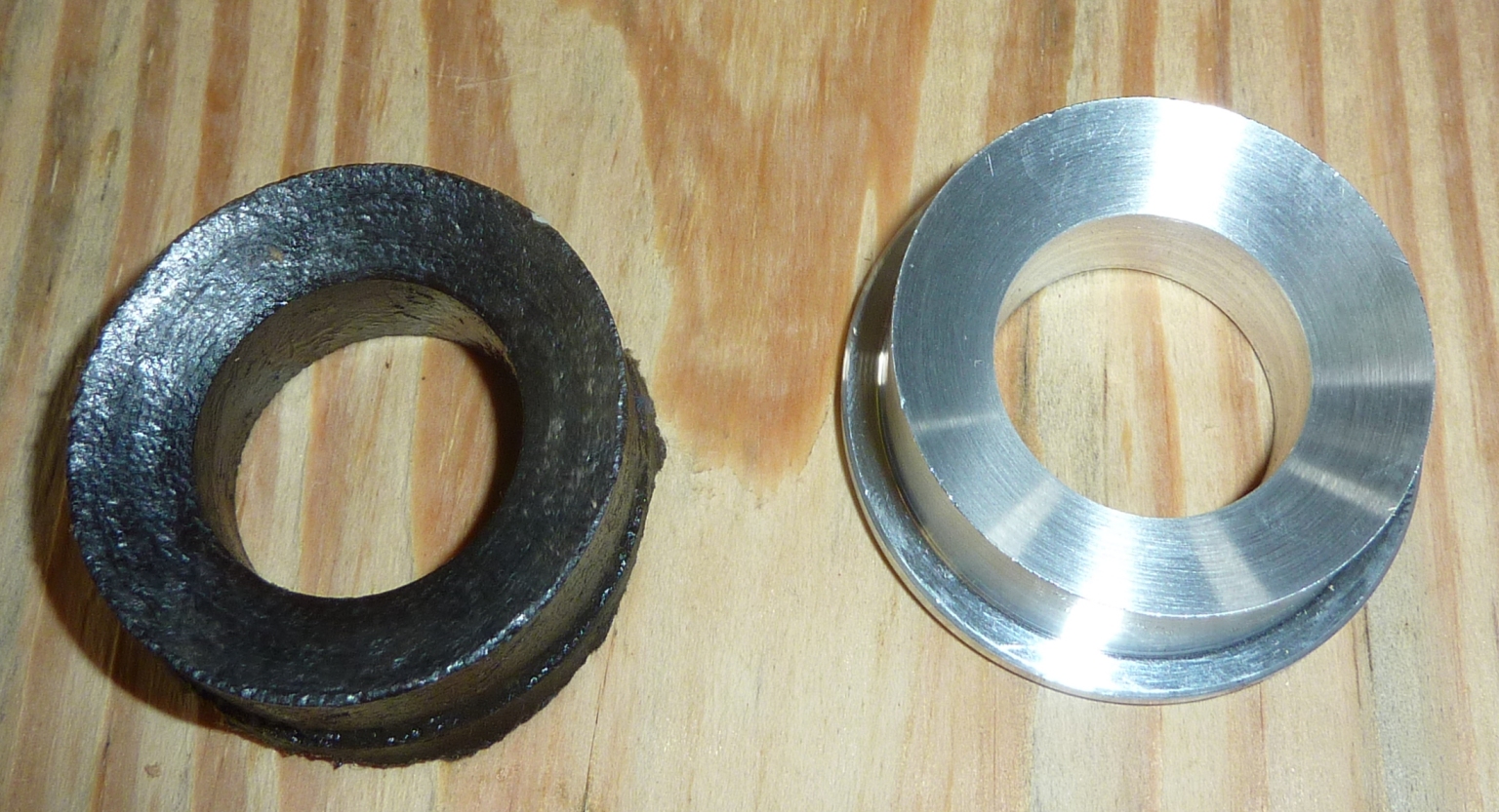
Here are photos of an old worn fiber packing gland and the new aluminum version, PN 1-319. Top on the left, bottom on the right.
On the left, the PN 1-2119 packing from Wag-Aero, on the right, 3/8" packing from McMaster-Carr, mentioned earlier in this article.
Above photos show a close-up comparison of the two packings. The 3/8" packing from McMaster Carr is on top, below is the packing from Wag-Aero. It actually measures 1/4" square. As Dave Rude mentioned earlier, the new packing that comes from Wag-Aero, PN 1-2119, requires three wraps of packing instead of the two wraps as shown in drawing 1-2119. I found the smaller packing was easier to work with. I cut it to 11.25" to accommodate three wraps. The drawing shows two wraps at 7.5". Ian Harvie had written to me a while back mentioning that he could only get one wrap of the thicker packing (that he had found locally in Australia) to fit in the stuffing box. He also mentioned that he smeared EZ-turn fuel lube over the packing to help make it easier to install and help with sealing the assembly. Again, I'd like to mention John Propst's article on oleo struts. Look for it here.
This photo shows a strut assembled with new parts. In fact, this photo is of an entirely new strut assembly, PN 3-433 as received from Wag-Aero. Notice that the packing gland sits high. I neglected to measure this one before installation, but my guess is that it sits nearly 1/4" high. It should compress some more after a few of my landings. I bit the bullet an ordered the new assembly from Wag-Aero because one of my struts needed repairs beyond my capabilities. I will probably send the old one to Dave Rude for repair and keep it as a spare, but installed the new one because I did not want the down-time while I shipped it to North Carolina.
Back
to the Aeronca Technical Information Main Page
|


