|
Hangar Construction Project
- Archives 2009
For more recent photos
go here.
Added
1/8/10 , updated 7/26/13. Click on any photo for a larger view.
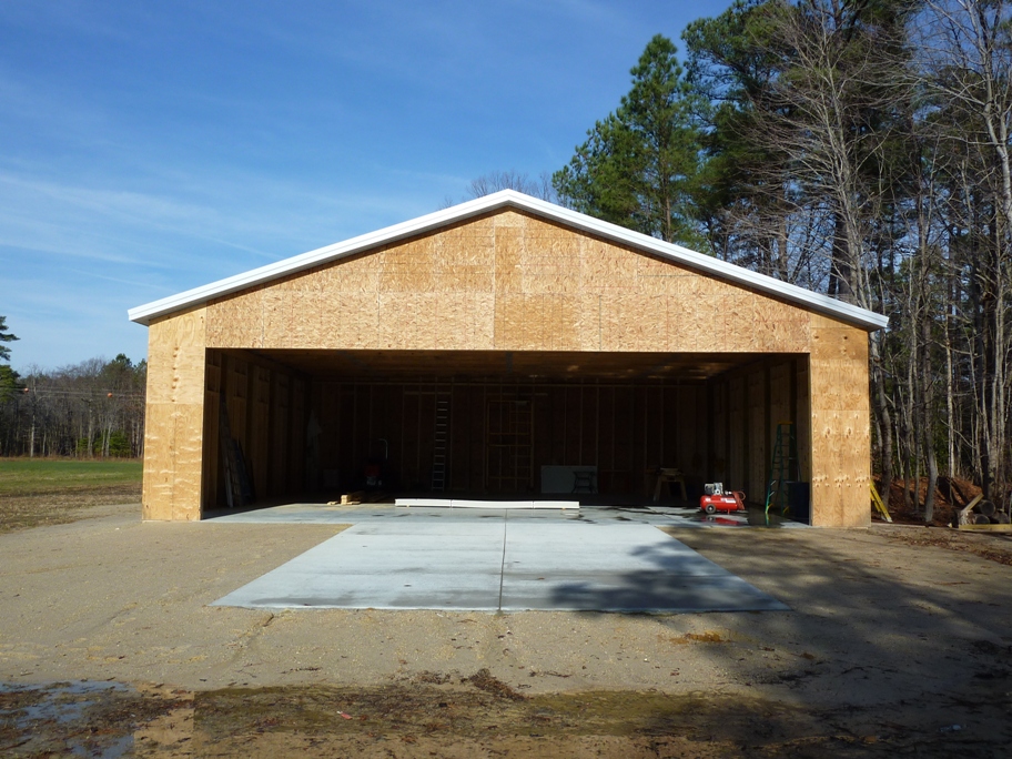
December 29, 2009.
Finally, all of the sheathing is done. I used 1/2" CDX ply on the corners
and OSB in between.
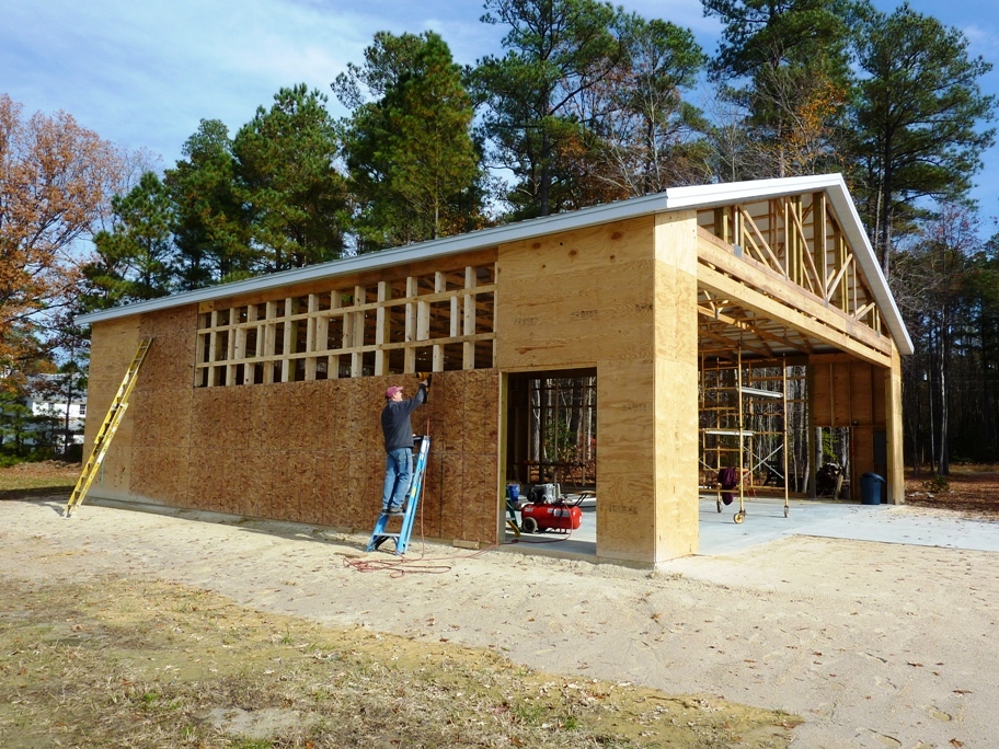
November 17, 2009.
Here, I'm installing sheathing using my old Bostitch pneumatic framing nail gun. Notice the
frame outs for the windows and doors.


November 11, 2009. I
hired an electrician to bring 200 amp service into the hangar from the house.
He also buried a conduit between the house and hangar for telcom/data lines and a
second conduit for future high voltage lines so I could control lights or other
devices in the hangar from the house. I will finish the electrical work
myself.
Local codes here allow homeowners to apply for a permit and do work on their own
place.

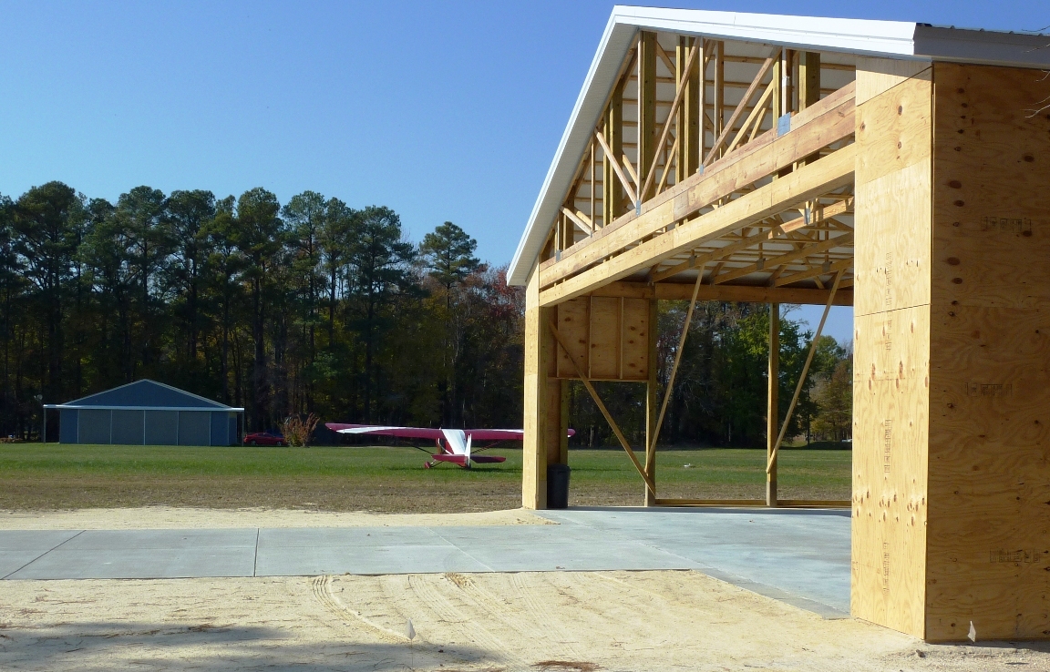
October 30, 2009. A
view of the hangar door opening from the inside. The clear opening is 42'
x 12'. Temporary diagonal braces are in place to help keep things square
until the framing and sheathing are complete.

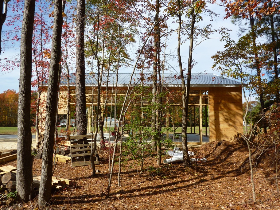
October 26, 2009. After
the concrete pour, my first project was to frame in the corners so they can be
sheathed with CDX plywood. Ply in the corners provides strength to avoid
racking. 2x6 studs are installed between the 6x6 posts on 24" centers. The
studs and posts are then faired out with 2x lumber to match the footprint of the band board and header.
Framing it this way will allow the future installation of insulation and
drywall, if I decide to someday finish the interior.
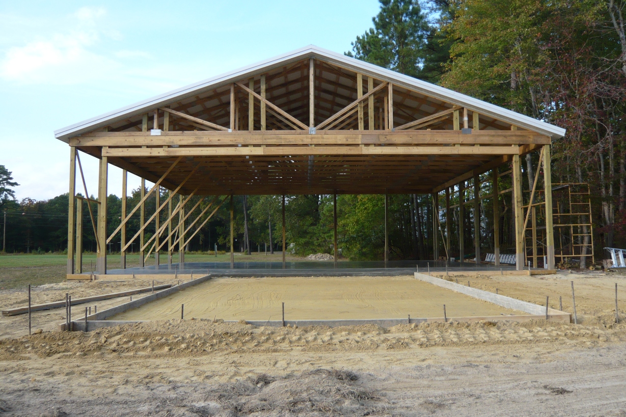
October 13, 2009.
With the main slab complete, work moves to the 20' x 32' apron.

October 12, 2009. I
hired a local concrete finisher to pour the 5" slab. The band board serves
as a former. Care is taken not to damage the tubing.

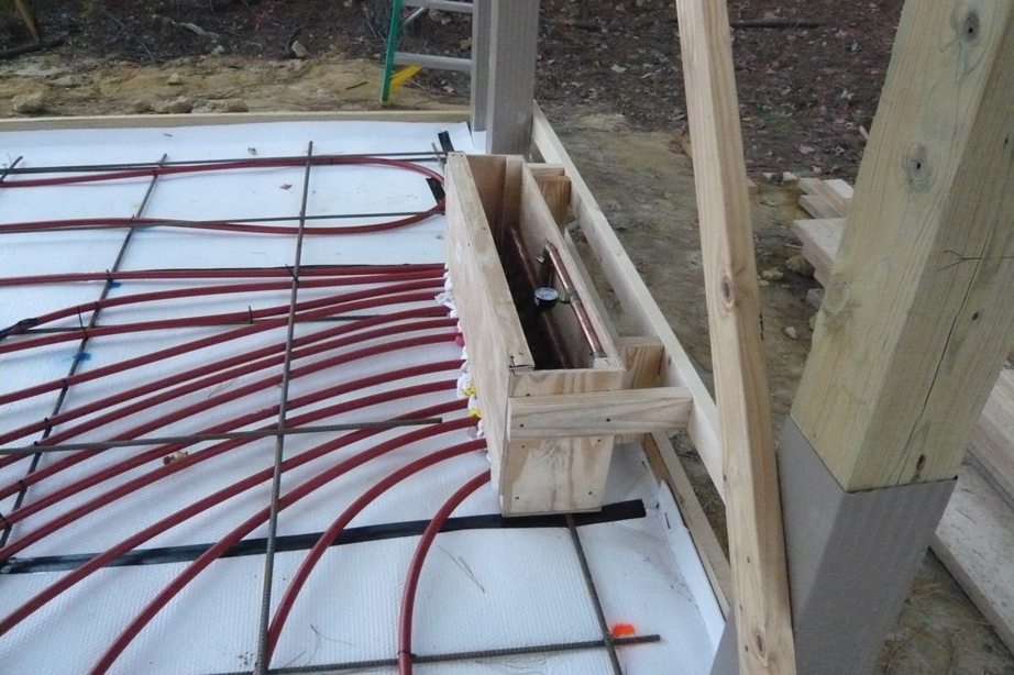
October 7, 2009. I laid out the tubing for the radiant
heating prior to the slab pour. After the base is prepared, a layer of
double-bubble reflective insulation is laid down. The insulation rolls up
the side of the band board. Once the insulation was down, the concrete
contractor laid down one layer of rebar in a grid pattern, 48" on center.
Once the rebar was down, I laid out the tubing in 6 equal length loops, each
connected to the input and output sides of the manifold. After all
connections were complete, I pressure tested the system. Following the
tubing installation, a second layer of rebar was laid down in an offset grid
pattern, 48" on center, so that the final rebar grid is at 24" on center.
Thus the tubing is sandwiched between two layers of rebar, helping to keep it in
position. The tubing is attached to the rebar with zip ties. The box around the manifold serves as a former for the concrete pour. Rags
are stuffed around the tubes where they enter the box to prevent the concrete
from flowing into the manifold box. After the cement set, the box was
cut out. I ordered the materials for the radiant heat from
Radiantec.
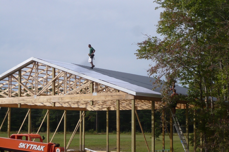
October 2, 2009.
Here, the contractor is laying the Fabral metal roofing over the reflective
insulation. A one foot overhang and soffit all the way around provides some protection
for the walls and improves looks.
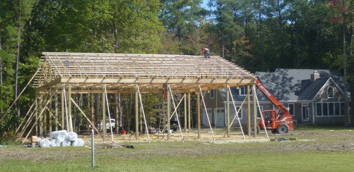
October 1, 2009.
Purlins made of 2x4's provide support for the roof insulation and roof metal.
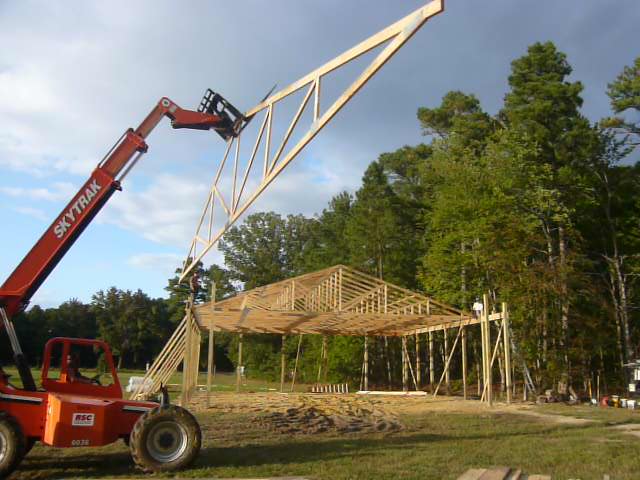
September 30, 2009.
A super-sized fork lift is the right tool for putting the trusses in place.
The span is 50'. Trusses are set on 4 foot centers. A double truss
is placed over the large door opening. After several designs, some that
included an attached shop, I finalized on a simpler design to reduce costs.
The south facing main door faces away from the prevailing northwest winds.

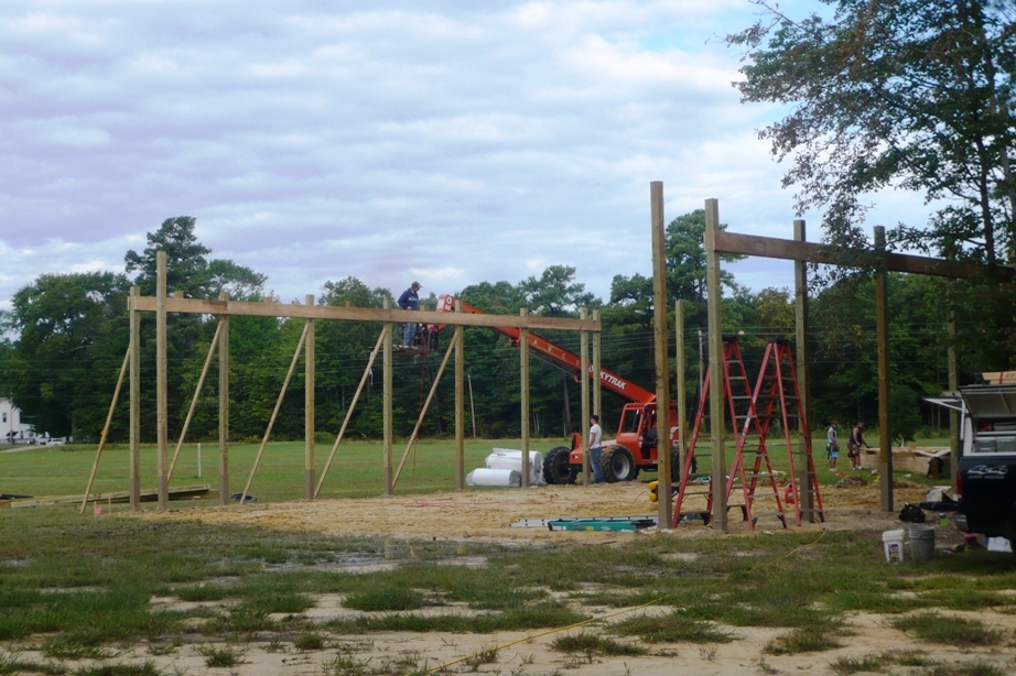
September 22, 2009.
A serious post hole digger is required. There are 22 6"x6" pressure
treated posts. Each post sits on concrete and is protected with a plastic
sleeve called, somewhat predictably, a "Post
Protector."

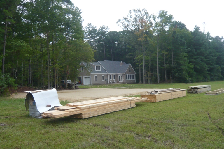
September 7, 2009.
The trusses are delivered first, then the other materials. I contracted
with National Barn Company to put up
the posts, trusses, and roof. The hangar will be 50'x50'x14'. Roof
pitch will be 4/12.

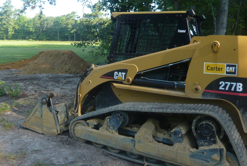
August 17, 2009. The
project begins with some fill dirt. The hangar is sited in a low area, so many
tons of fill will raise the floor to keep things dry. A local contractor
provided the fill dirt and skid steer work, and leveled the site using a
transit. Previously, I cut and removed about 15 trees to allow for the
necessary 125 foot setback of the hangar from the runway. As with the
house project, the goal was to remove no more trees than necessary.
Back
to the Hangar 9 Aeroworks Main Page
| 