|
|
|
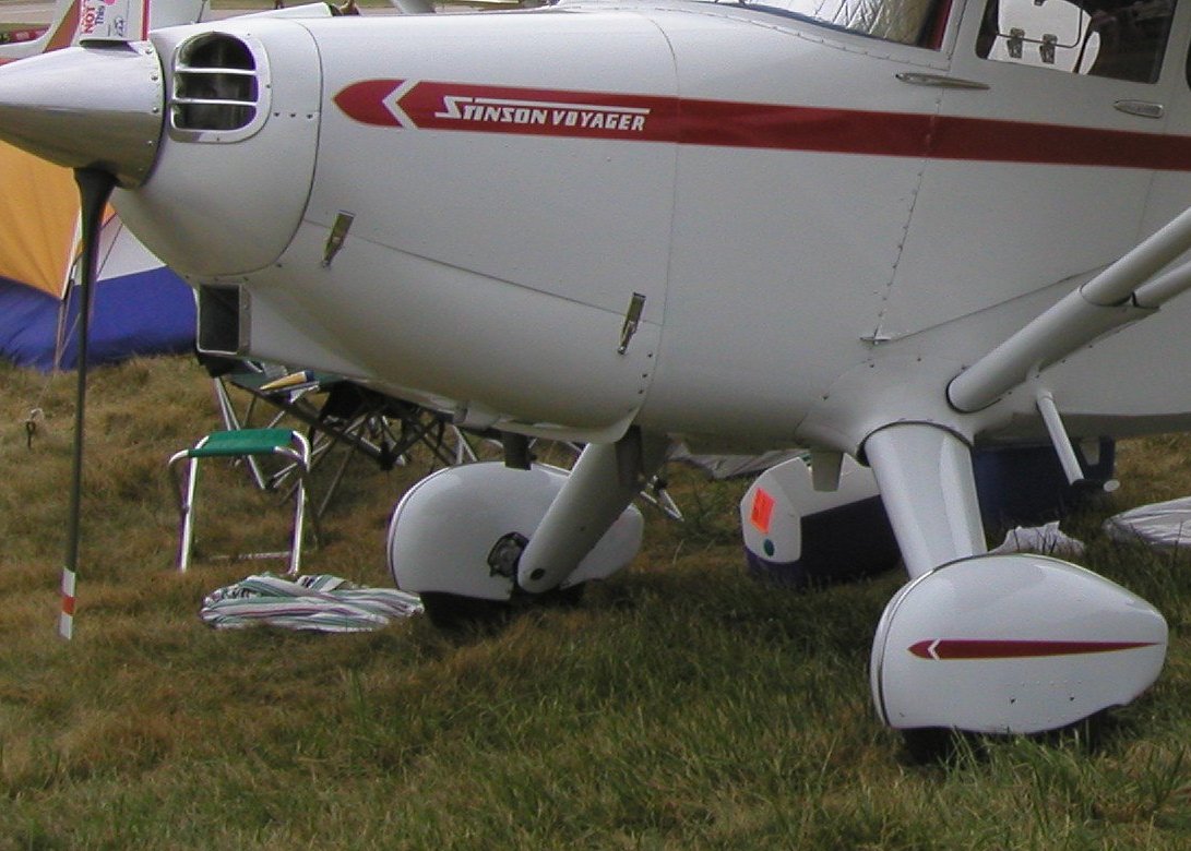
Stinson 108 Series - Cleveland Brake Conversion - Rear Mount Added 8/8/07 - Updated 1/24/13 Click on images for a larger view. Stinsons originally came with Goodyear hydraulic disc brakes. Most parts for those brakes are no longer in production so maintenance has become problematic. A popular option is to convert to modern Cleveland hydraulic disc brakes. Conversion kits are available from Univair. In years past, the conversion required a field approval and a 337 form. Now, the Cleveland brakes have been added by Univair to the Stinson Type Certificate so the change can be accomplished by an A&P with a log book entry. The conversion provides for operational reliability and easy maintenance. The down-side of the standard conversion is that the forward mounting of the brake caliper requires major surgery to the wheel pants to clear the caliper. This alters the stock appearance in a way that many deem unsightly. The photo below shows a wheel pant modified to accommodate the standard caliper location. This is a nice example, and the cutout for the caliper was minimized, but still, it requires quite a bit of surgery to the wheel pants.
Cleveland brake conversion - standard forward caliper location To avoid this, numerous owners have altered the installation to mount the caliper aft of the axle. requiring only minor trimming of the wheel pants. The change requires drilling alternate holes in the caliper torque plate mount so that the mount and caliper may be rotated aft and reconfiguring the hydraulic line. Many have done this successfully which no operational problems. Before you consider this alternative location, discuss the change with your A&P or IA. Some may require a 337 form since this installation is slightly different than standard. Some IA's, recognizing the benefit of the alternate location, may consider this a minor change and just do a log book entry. In any case, any work of this type must be done under the supervision of an A&P and in compliance with FAA regulations. The photo below shows an installation with the caliper rotated to the rear. The installation shown is not on my airplane - I had the standard mount on my plane (since sold). But I wish I had known about this alternative before I cut my wheel pants years ago.
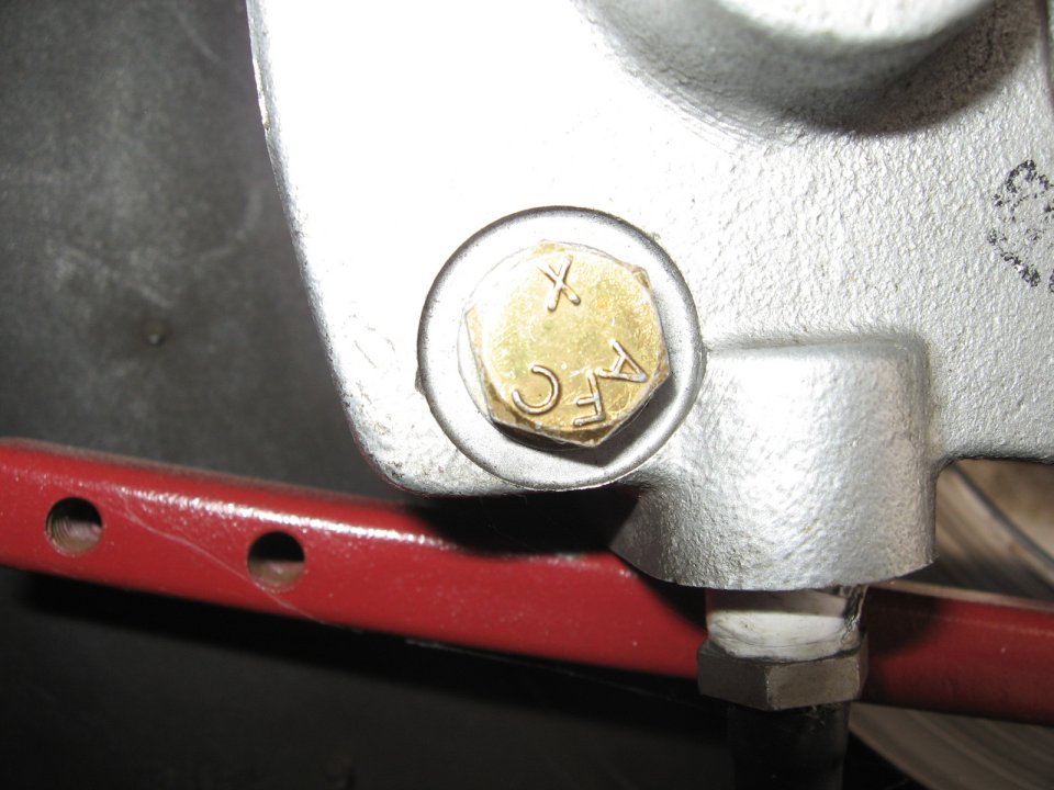
Aft mounting of the caliper provides for a cleaner installation. The aft installation requires drilling additional mounting holes in the caliper torque plate, roughly midway between the existing holes. (Sorry, but I don't have photos of the bare plate.) This can be done on a drill press with sharp drills and cutting oil. Not a job for the faint-hearted, you may want to have this done by a machine shop. You can use the torque plate from the opposite wheel as a pattern, clamped to the plate you are drilling. Consider the location of the holes carefully. In the example shown, the holes were drilled midway between the existing holes which provided minimal clearance between the caliper and the lower wheel pant bracket. It would be best to shift the hole location slightly down or counterclockwise, about 1/32", so the caliper ends up just a bit higher or clockwise, than shown in this installation. Update: A Stinson owner reported in January, 2013 on the Yahoo Stinson Discussion Group forum that he was working with Parker Hannifin (maker of the Cleveland brake conversion) for the approval and production of an alternative torque plate drilled for the aft caliper location. As I hear additional news on the progress of this effort, I will post it here.
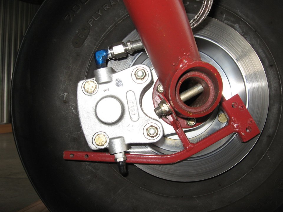
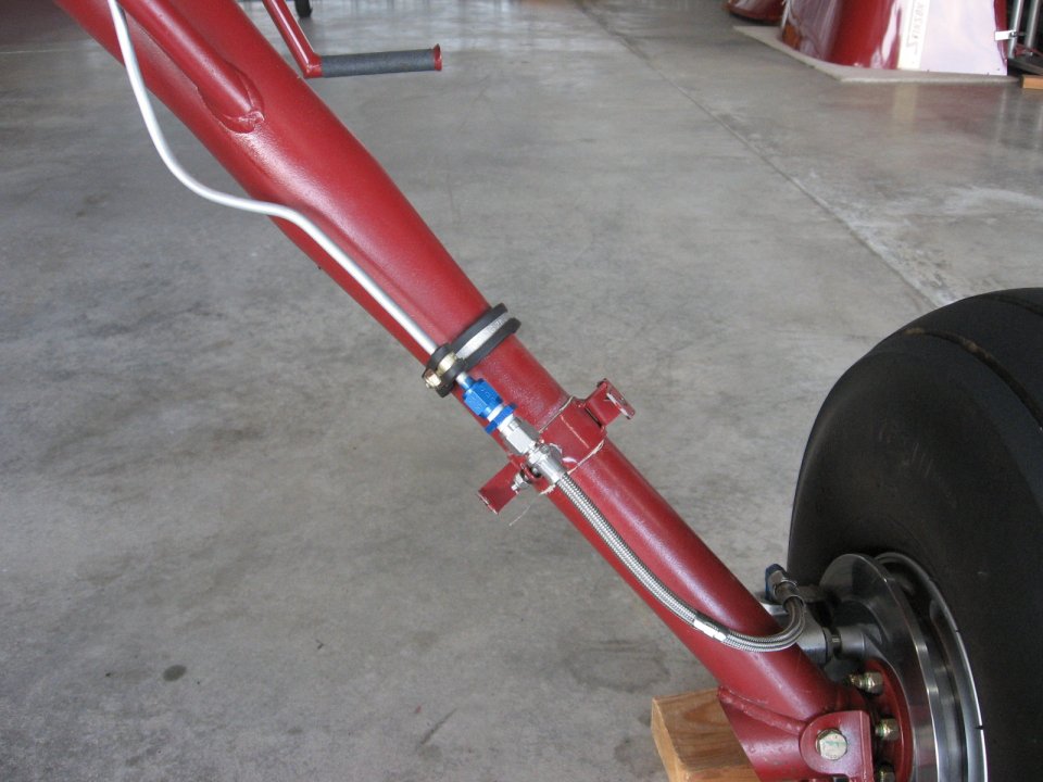
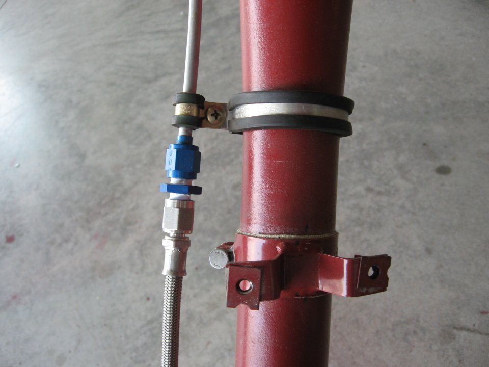
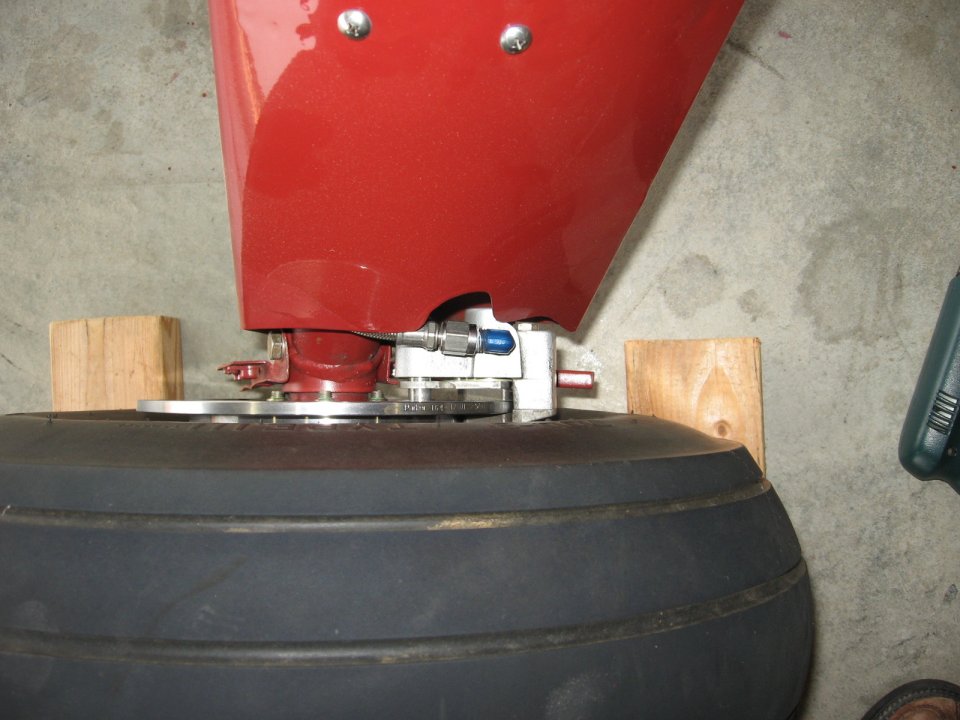
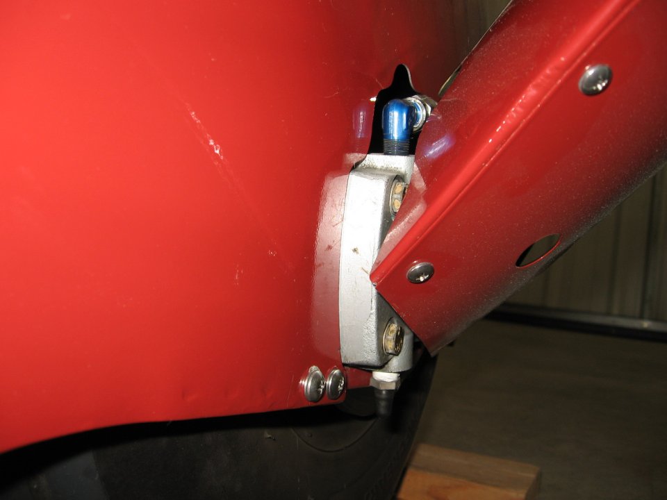
Two photos of left wheel showing tight clearance between caliper and wheel pant bracket. Adjust caliper location by adjusting location of holes drilled in torque plate. It appears that the standard location was designed to simplify installation, requiring only the addition of a short length of flex tubing to the standard aluminum brake line used with the Goodyear installation. The aft location will require some modification to the brake line. Start by gently bending the aluminum brake line which runs down the back of the gear leg around to the front of the gear leg. There will be a bend in this line where it was curved around the back of the gear leg...you will want to straighten some of this bend out because otherwise the tube could contact the inside of the gear leg fairing. Actually, the bend could be a little less than shown here, though in this case the line does not touch the fairing - but it is close.
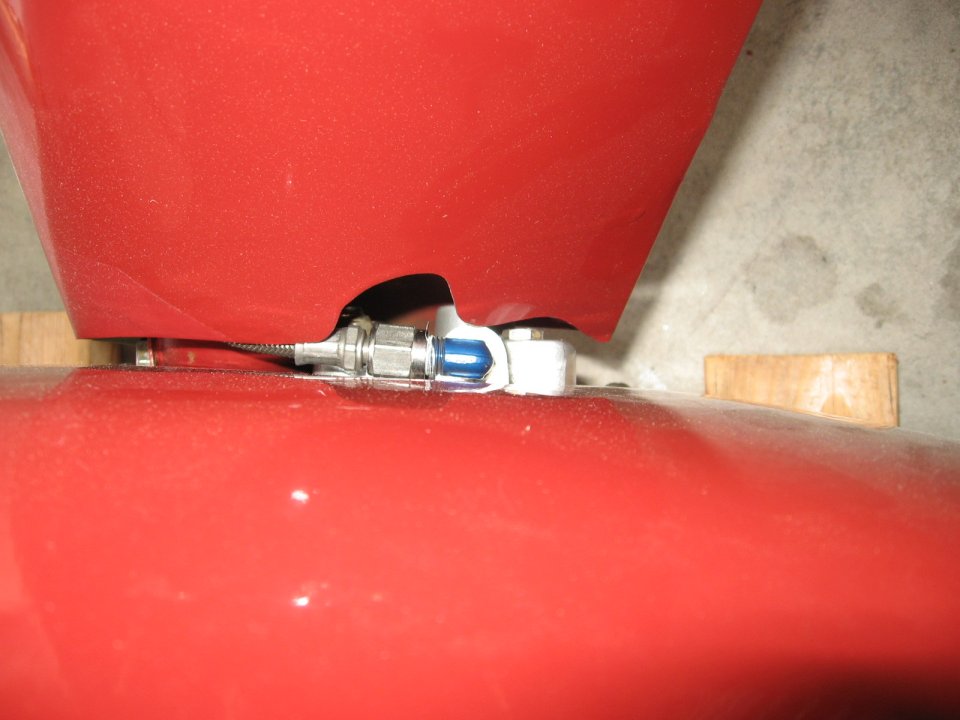
Routing of brake line is moved to the forward side of the gear leg. The tube is secured to the gear leg with a couple of Adel type clamps where the gear tapers down in diameter to 1 3/4 inches. These clamps are MS 21919 clamps. The large clamp which fits around the gear leg is a DG 28, and the small clamp which secures the brake line is a WDG 4 (See Aircraft Spruce catalog or similar hardware supply). A single 10-32 machine screw secures the small clamp to the large clamp and secures them to the gear leg while holding the brake line in position. Take a small tubing cutter to cut the line, and beg or borrow a flaring tool to flare the end. Remember that aircraft applications use a different flaring tool (37 degrees) than is used in the automotive industry. Before flaring the tube don't forget to slip an AN818 -4D coupling nut over the tube. An AN832 -4D ( or AN815 -4D) universal union is used to couple to the flex line going to the brake. As seen from the pictures, the flex line comes into the top of the brake cylinder, and is parallel to the inboard sidewall of the tire. It is important that the line leads into the cylinder from this direction, and not from straight down the back of the gear leg as the tube did with the Goodyears. The caliper must not be restricted in its ability to "float" on the pins, and thus the reason for routing the line around to the front of the gear leg. The flex hoses are Parker Stratoflex and the same type as provided in the kit, just a bit longer. The length of the hose is measured from sealing surface to sealing surface, and these are 11 inches long. These were ordered from Precision Hose Technology of Tulsa, Oklahoma - 918-835-3660. Aircraft hoses are their only business, and they will ship your order out in short order. Tell them the application and they will know exactly what type line you need...you just need to give them the length. The hoses, one for each side, are about $30-$40 each.
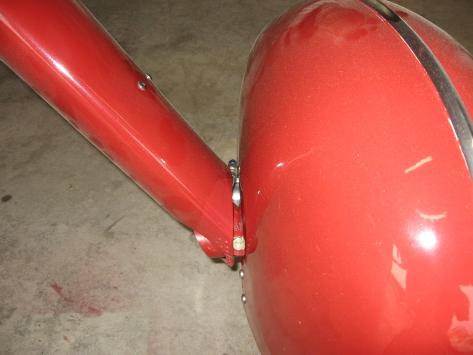
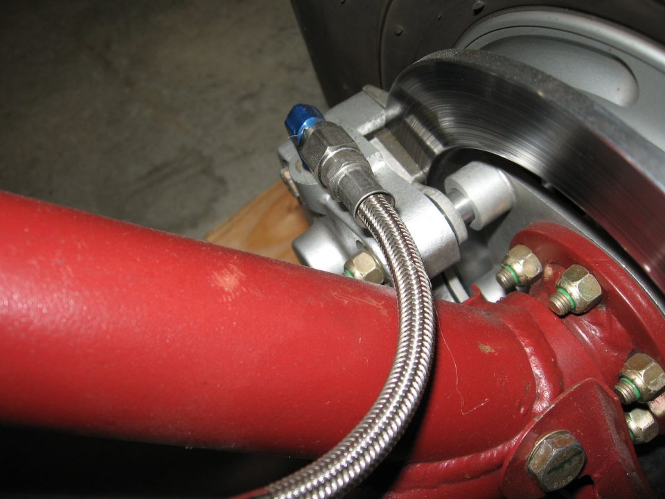
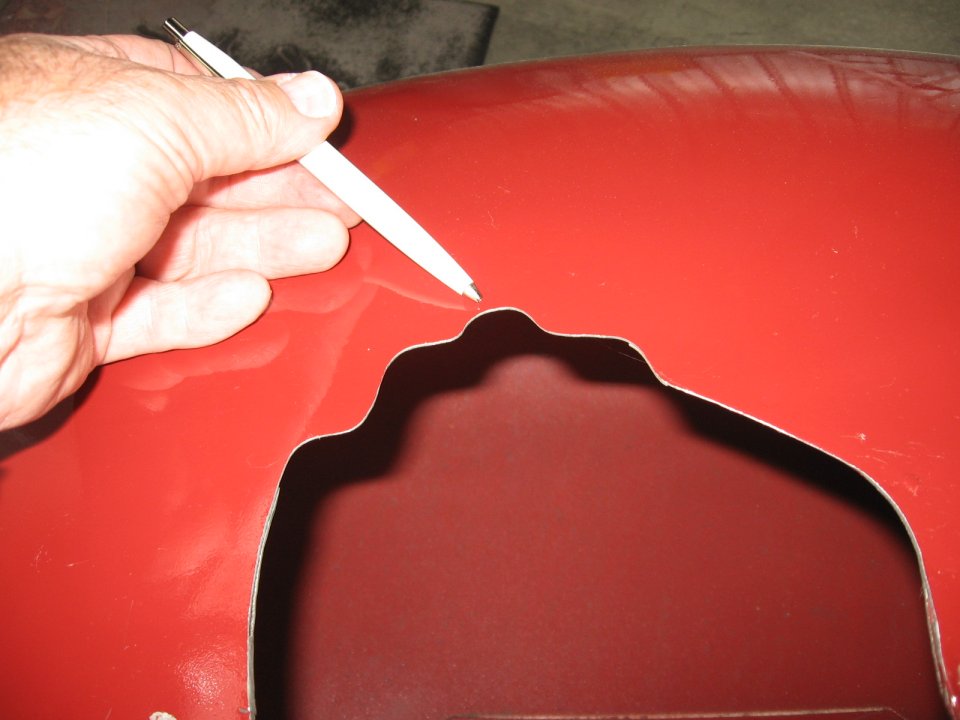
Flex line coupled to aluminum brake line and connected to caliper. The wheel pants will need some trimming to clear the caliper. This can be done with a Dremel tool or rotary file. Go slow and check your progress frequently. The notch in the top of the opening on the wheel pant in the second photo below, which the installer thought would be needed to clear the AN fitting on top of the caliper, is not actually required, so don't enlarge there.
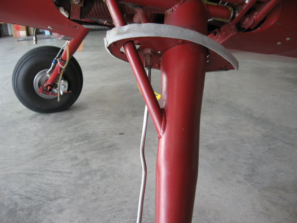
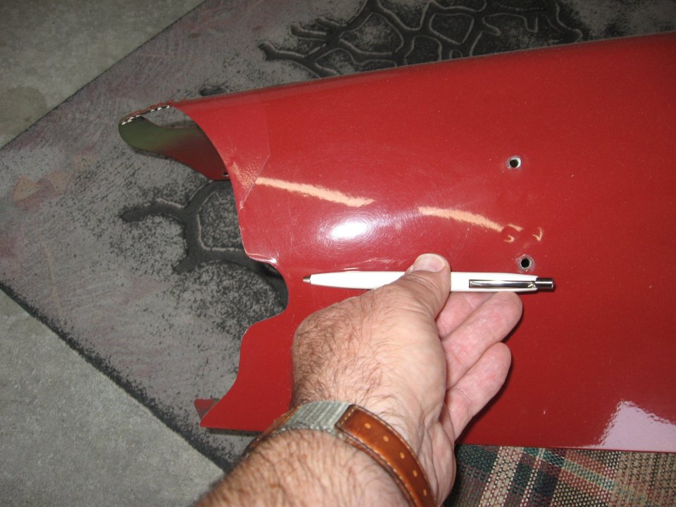
Trim wheel pants to clear caliper. The photos below show the gear leg fairing. No modification is required. You can see that the notch at the bottom of the gear leg fairing where the original line came out to the Goodyear caliper is no longer needed, but it's there so you have to live with that. If you are making new gear leg fairings using the old as a pattern, you can eliminate the notch.
Gear Leg Fairing
Completed Installation
|